Stacked Turntable Module (method 3) Building Instructions
This page shows how to build a module for my general-purpose "stacked turntables" orrery design, described on my orrery pages: Stacked Turntables, method 3.
Contents
3 1/2 Modules with Interchangability
Earlier prototype: Two Modules with a Base and Top
3 1/2 Modules with Interchangability
Here is an overview of how multiple turntable modules fit together. For more detail on how to build just one of these modules, see the section below, The Original Prototype.
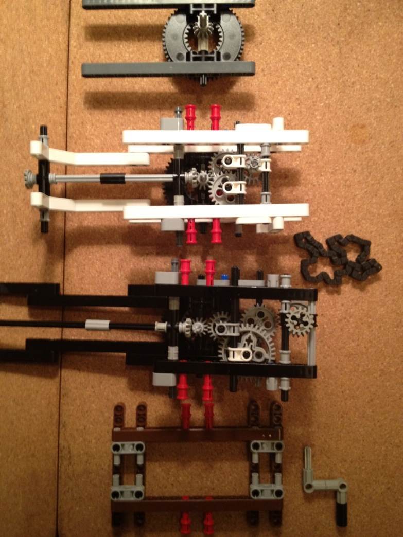
Here are five parts which will be assembled into a working orrery.

components of a modular orrery
From bottom to top, the parts are: A "base", two full-size modules (with "Luke" and "R2D2" to illustrate the rotational maths article), the 3rd module (upper-right) and a small 4th part (yellow, upper-left).
The Base
This module represents the base of the entire finished machine. It would probably be bigger, because it needs to include gears to make the bottom-most turntable module turn at the desired proper rate.
")
base (top view)
")
base (one layer removed)
")
base (more parts removed)
In my abbreviated geartrain notation, the gearing in the base is:
Central shaft drive: input = +12 -> 20+ = output (central shaft) Drive for first module: input = +1 -> 20+16 >ooo> 40+16 -> 56 = output (first turntable module)The resulting ratios are 3/5 for the central shaft and 1/175 for the turntable of the first module. More important is the ratio between the two: 1/105. The first turntable will turn onece for every 105 turns of the central shaft.
First Module
Here is the first full module. It will sit on the base.

full view

bottom view

side view

top view

reverse angle closeup
The gearing is:
First turntable module (Luke): input = +12 -> 20+8 -> 36+16 -> 24 -> 24+16 >ooo> 56 = output (next turntable)The overall ratio is 8/315 ≈ 0.025397. This is the ratio of the central shaft rotation rate to the rate of the 2nd turntable, from the rotating reference frame of the 1st turntable. See my article on rotational math.
Now we'll add this module to the base:

alignment

in place

locking pins engaged
Now we have the base with one module:

base and first module assembled
This module uses a chain to drive the turntable of the module above it. When that next module is added, the chain will fit around the second module's turntable like this:

showing how chain engages next turntable
Second Module
This will sit on top of the black module.

full view

bottom view

side view

top view

reverse angle closeup
The gearing is:
Second turntable module (R2): input = +12 -> 24+8 -> 24 -> 20+8 -> 56 = output (next turntable)The overall ratio is 1/35 ≈ 0.028571. This is the ratio of the central shaft rotation rate to the rate of the 3nd turntable, from the rotating reference frame of the 2nd turntable. See my article on rotational math.
We assemble the same way, but we also have to add the chain to link it to the first module:

before adding the chain

after adding the chain
Third Module
This module uses the large turntable as its base, but is meant to accomodate the new small turntable (made from piece 99009 and 99010) on top. Thus, the bottom of this module looks like the bottoms of the first two modules, but top of this module looks different.

full view

bottom view

side view

top view

reverse angle closeup
The gearing is:
Third turntable module: input = +12 -> 24+12 -> 16 -> 16+8 -> 28 = output (next turntable)The overall ratio is 3/28 ≈ 0.10714. This is the ratio of the central shaft rotation rate to the rate of the 4th turntable, from the rotating reference frame of the 3nd turntable. See my article on rotational math.
4th Module
This module uses the small turntable as its base, and is only a "half module" because it has no support for another module. However such support could be added easily if you wanted another module.

full view

bottom view

side view

top view

reverse angle closeup
As an alternative to adding a full module, the next planet above this one could be added using the differential housing. See my discussion of 4 ways to use the differential and other parts of my main orrery building blog.
Each of the 4 modules includes a radial axle, resembling the driveshaft that connects the transmission to the differential of a rear-wheel-drive vehicle such as a truck.
This is meant to facilitate a miniature orrery mechanism at the end of the arm, similar to that on the outermost planets of my Model D and Model G orreries, and the outermost two planets of my Model H.
In an actual complete design, the arms would probably be longer, and you'd need to add counterweights to keep everything balanced and running smoothly. See several examples of this in my orrery blog.
Fully Assembled
When all the modules are put together, the completed orrery looks like this:

complete 4-module assembly
Everything is set into motion by turning a crank attached to the base.

after running it for a bit
The first three modules (those with a large turntable as their base) are completely interchangeable. Here are two examples, both are fully functional:

leaving out the black module

black and white modules swapped
To change the original into one of these, all that is required is to unlock the red locking pins, and where applicable remove the chain that is part of the black module; then re-stack the pieces in a different order.
Earlier prototype: Two Modules with a Base and Top
Here is the first prototype of stackable modules using just two full turntable modules. For more detail on how to build just one of these modules, see the section below, The Original Prototype.
Here are four modules which will be assembled into a working orrery.
The Base
This module represents the base of the entire finished machine. It would probably be bigger, because it needs to include gears to make the bottom-most turntable module turn at the desired proper rate.
First Module
Here is the first full module. It will sit on the base.

bottom view

side view

top view

from another angle
Second Module
This will sit on top of the black module.

bottom view

side view

top view

another angle
Top Module
This is could be the start of a third module, but in this case it's just a minimal top section.
This shows how you start building a module. All the modules have the same thing in the center: a vertical axle (five units long, part 32073) held in place with an axle connector #2 (part 32034), a double bevel gear (I used part 32270 but 32269 would work too) and a few small pieces to hold everything in place.

bottom view

side view

top view

another angle
Assembled
As you can see in the pictures, the first three parts (the base and the black and white modules) have some red pins, part 32054. The steps for assembly are:
- Place the base flat on the table.
- Put the black module on top of the base, so that the red axle joiner (part 6538) fits over the vertical axle in the center of the base.
- Push it down into place so it is aligned as snown below
- Slide the four red pins in, so that the base and the black module are locked together.
- Use the same technique to add the white module and the "minimal" gray top module.
- Connect the chain around the second turntable, so that the little gear on the black module turns the white module
- Pick the whole thing up and add the little crank to the bottom.

the finished assembly
Here is the original prototype for my third modular stacked turntables design. (Two earlier ideas didn't work out too well because of implementation details such as friction).
Multiple modules like this one can be stacked one above another, and the gears allow each module to revolve at a separate rate.
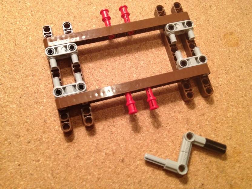
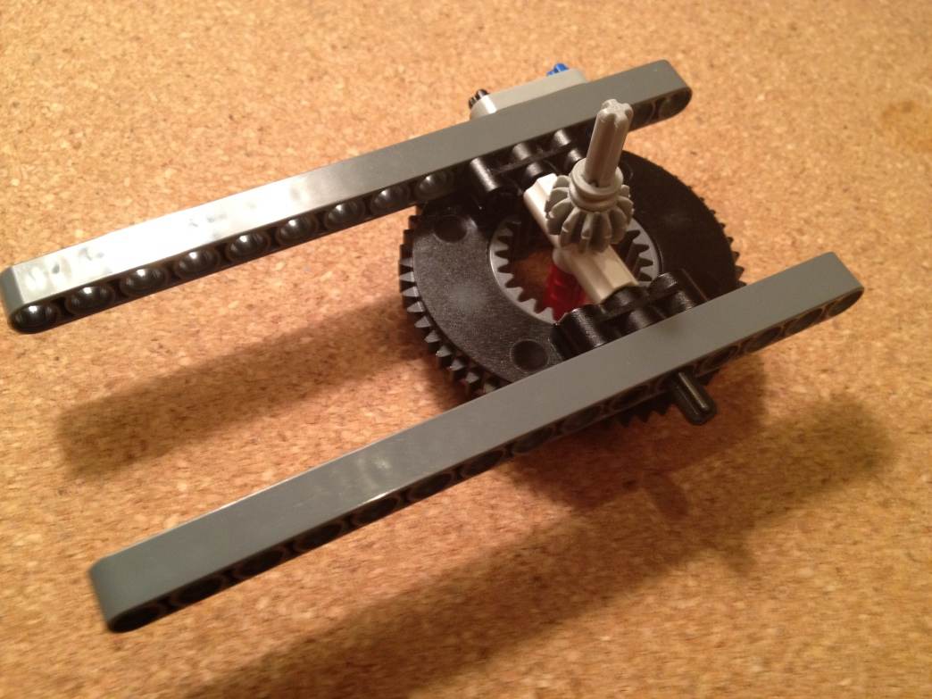
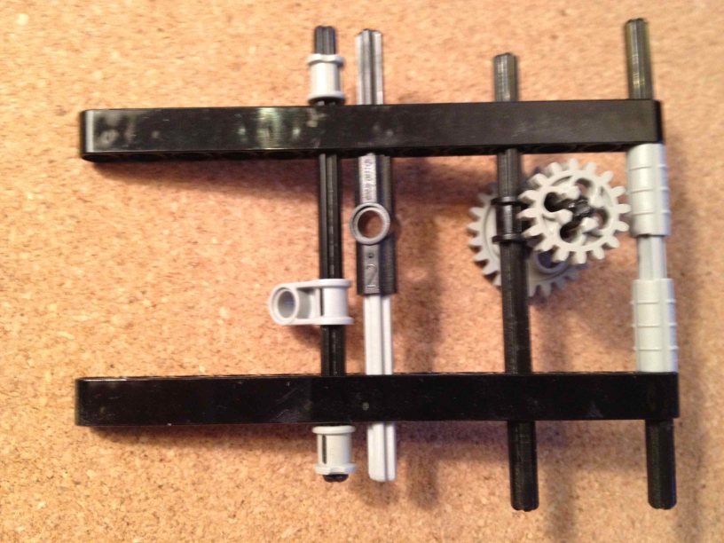
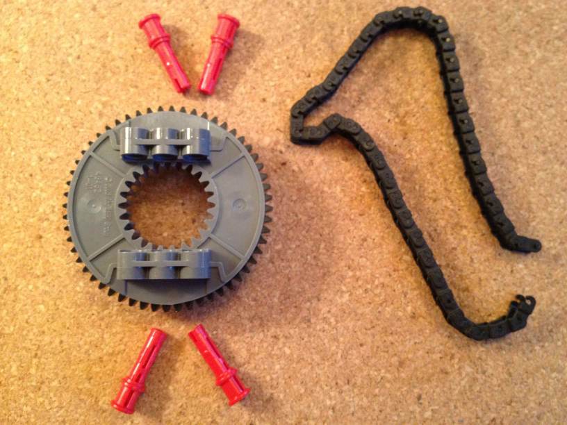
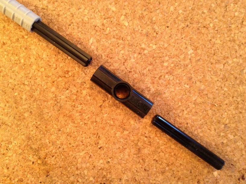
We start with a LEGO turntable (the new style type shown here, although this design can be adapted to use the old style instead). We connect it to a couple Technic beams:
This construction represents the top of the module that sits below the module that we're about to build.
Now turn this over so the gray side faces down, and the black side faces up. All turntables in a stacked set should face the same way. Each turntable will be turned by a bunch of gears and a chain that are supported by the layer below it.
Now we add an "arm" that extends out some distance. The length of this will depend on how far away this "planet" is from the "sun". We use these small connectors:
|


Here's the far end of the arm:
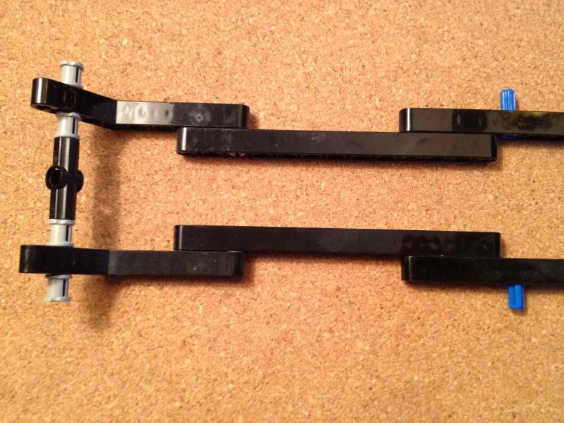
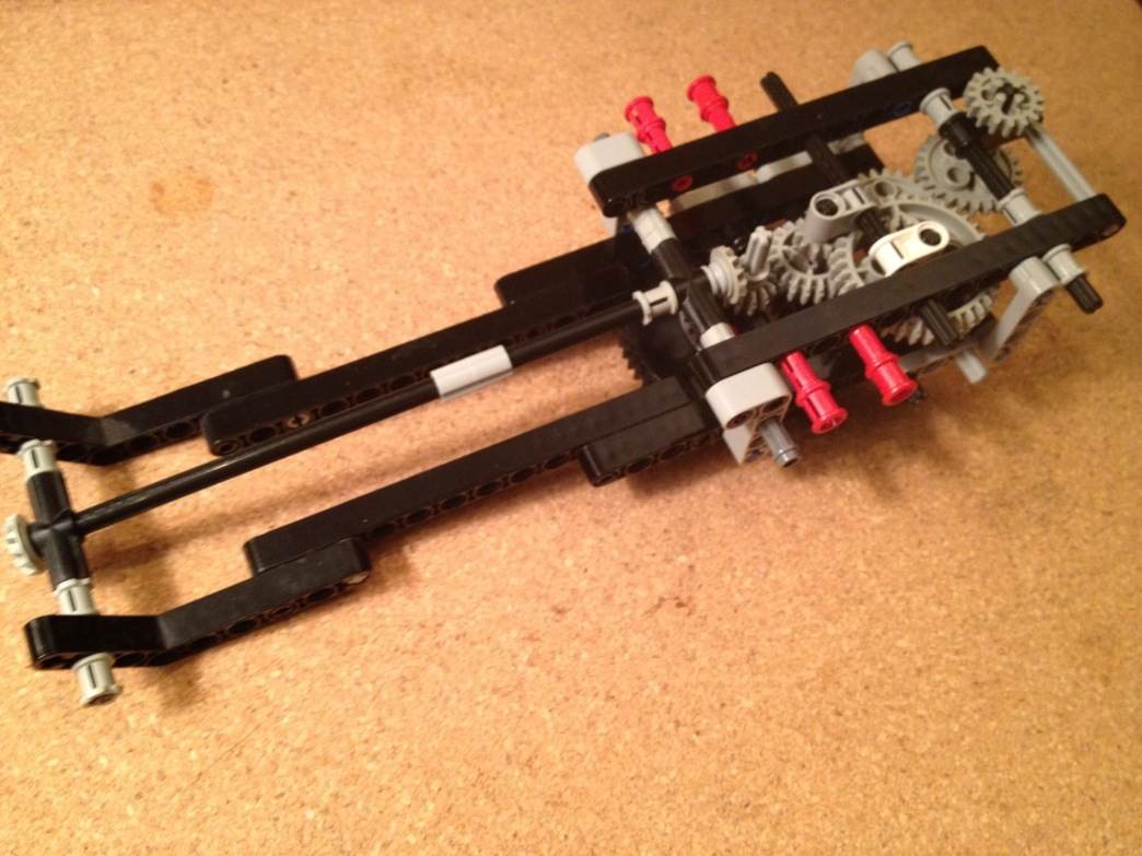
The "near" end will have a bunch of stuff that holds the gears. I've attached a few pieces already, and the rest are added in the next several steps, below.
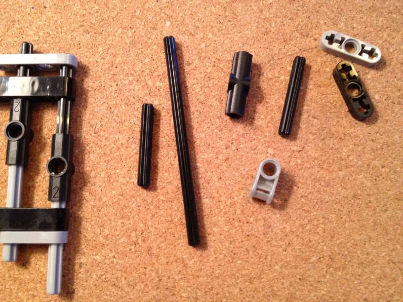
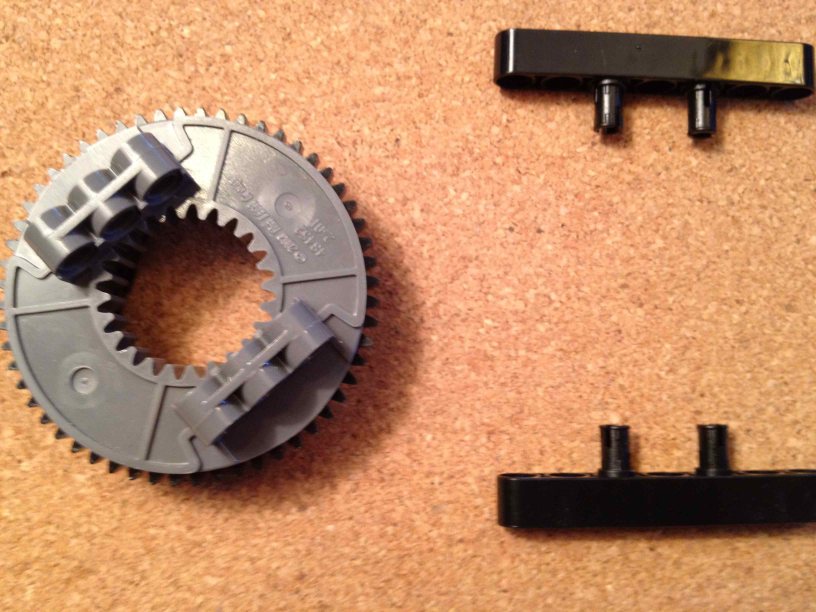
In addition to some longer axles and more of the pieces shown above, we use a few new pieces:
|


We want to attach the arm and these new pieces (black side) of the turntable. Before:

before
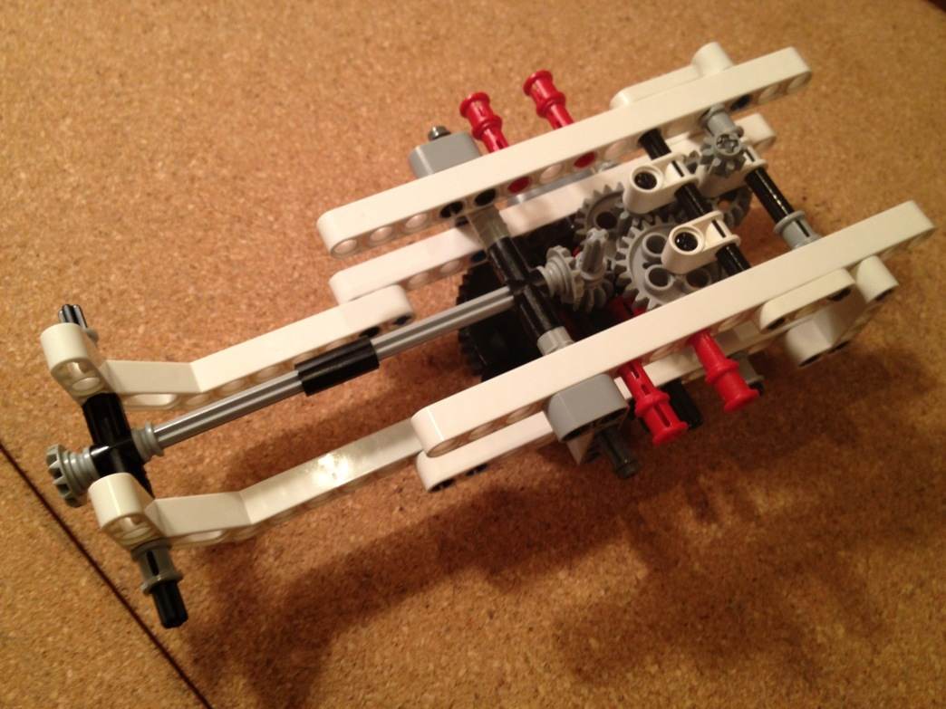
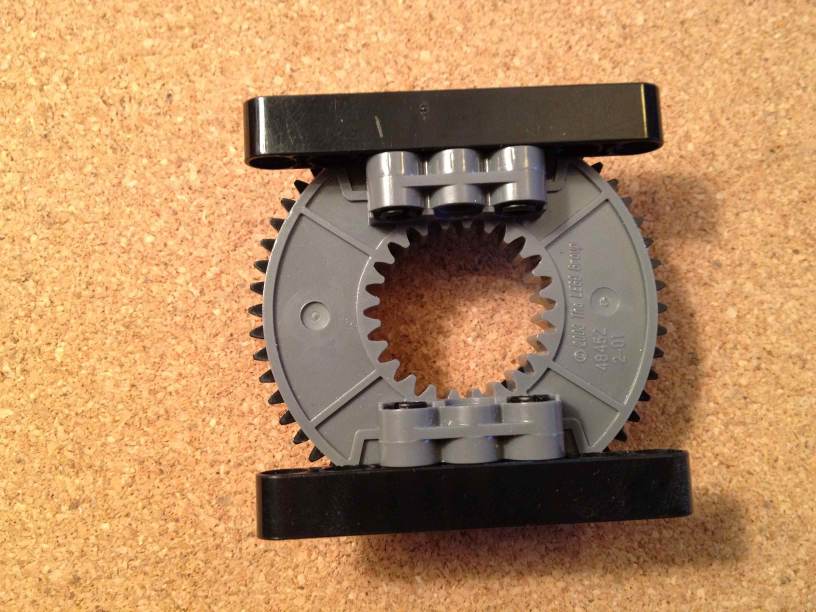
and after:

after
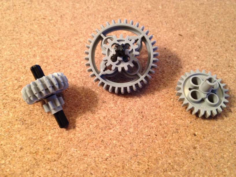
We've also added a vertical axle in the center. This axle turns freely and extends through all the levels of the mechanism. On this we want to add a gear:
In my abbreviated geartrain notation, the gearing for this example will work like this:
16 -> 20+8 -> 36+16 -> 24 -> 24+16 >ooo> 56In English, reading from left to right, we have a 16-tooth gear meshed with a 20-tooth gear,
which is attached by an axle to a 8-tooth gear that is meshed with a 36-tooth gear,
which is attached by an axle to a 16-tooth gear that is meshed with a 24-tooth gear (an idler),
which is meshed with another 24-tooth gear,
which is attached by an axle to a 16-tooth gear that drives a chain which goes to the 56-tooth gear on the turntable.
The overall ratio is:
driveshaft rate = 20/16 × 36/8 × 24/16 × 56/16 × output rate
= 29.53125 × output rate
In other words, the central shaft will turn 29.53 times faster than the turntable at the top of this module. This ratio just happens to be only 0.00224 of a percent larger than the average number of days in a lunar month, i.e. the number of days from each full moon to the next full moon — so this mechanism could be part of a clock that shows the phase of the moon. It is so accurate1 that you could run it for 100 years, and its indication of the full moon would still be within a single day (on average) from the real full moon.
Back to the building...
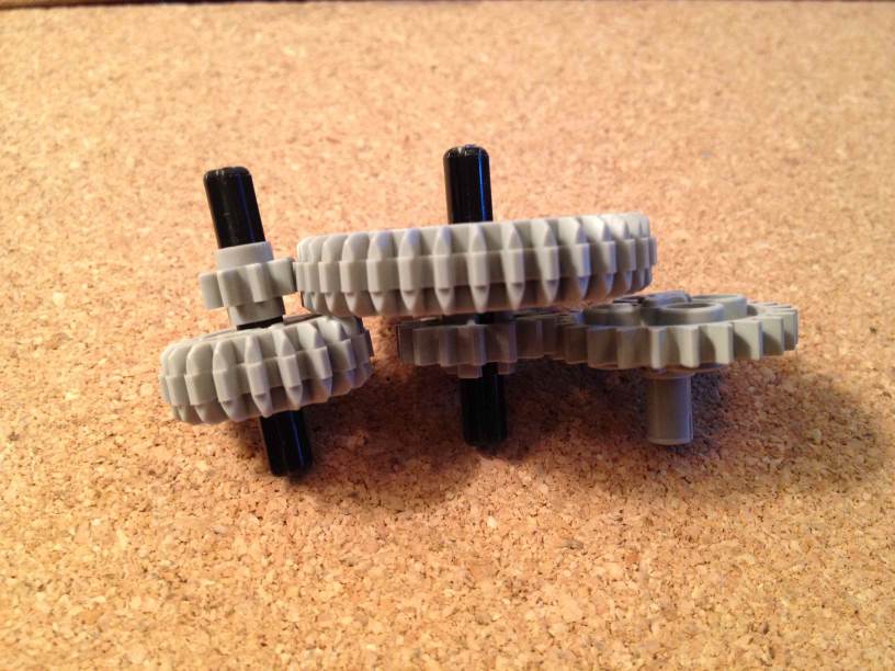
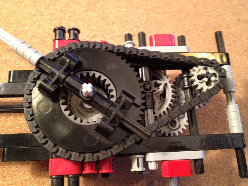
In the picture above, notice there are a few empty holes, in seemingly arbitrary positions. These are going to hold the next several gears in our geartrain:
The specific gears you pick and how they connect to one another depend on the exact rotation rate you need for this planet. See my page on LEGO gearing with a table of ratios.
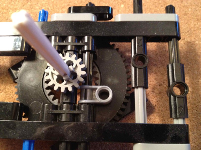
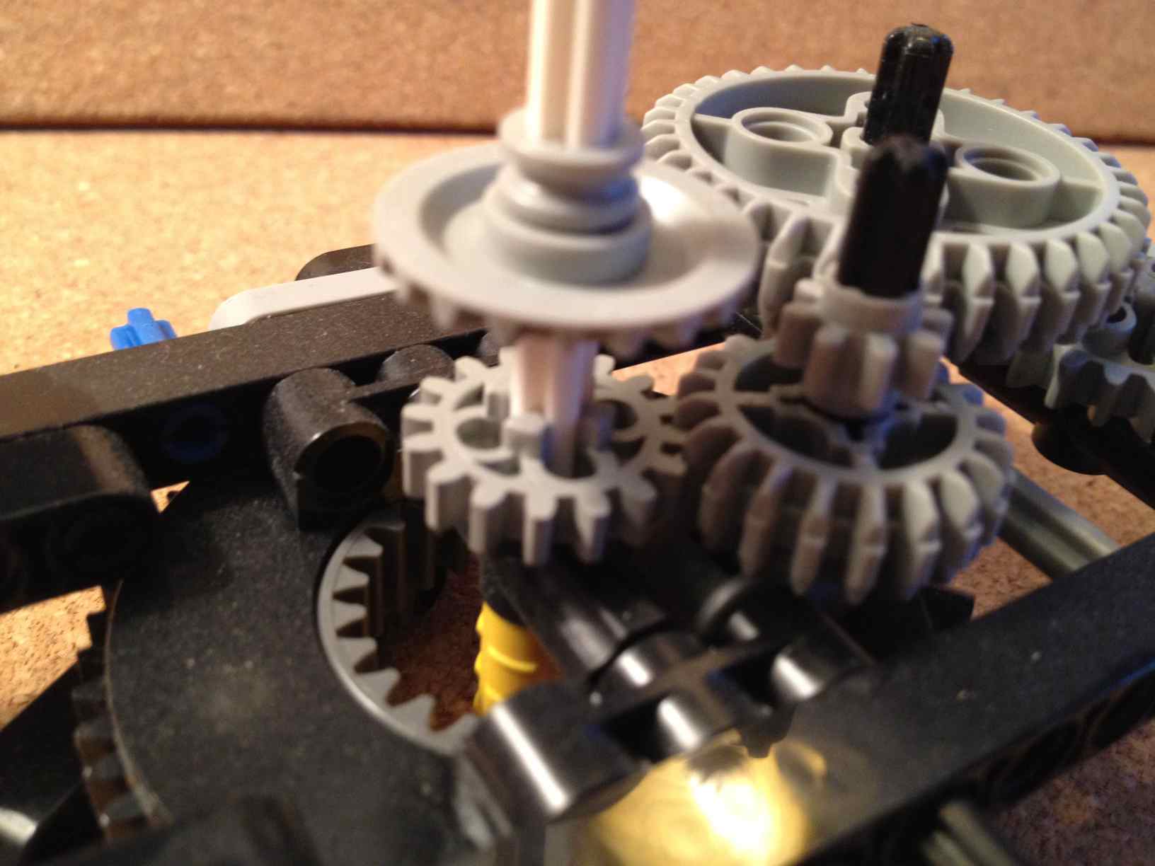
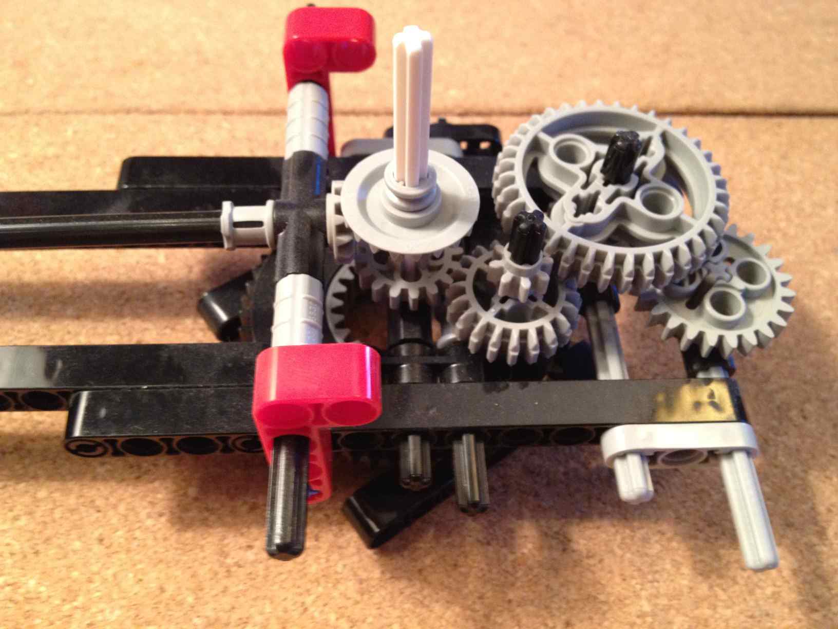
In this case the gears will connect like this:
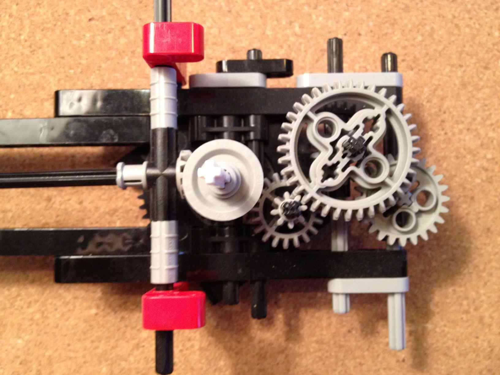
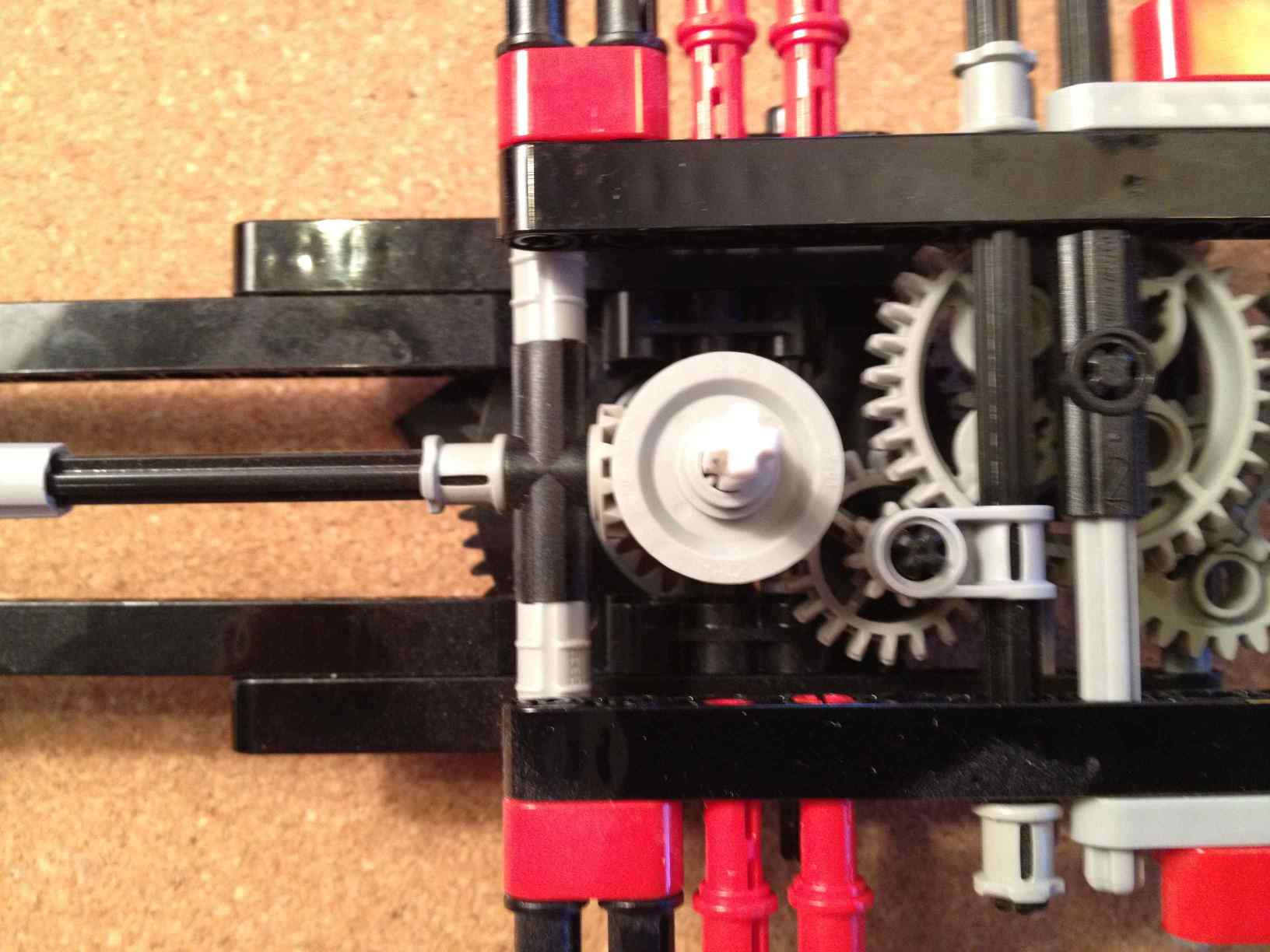
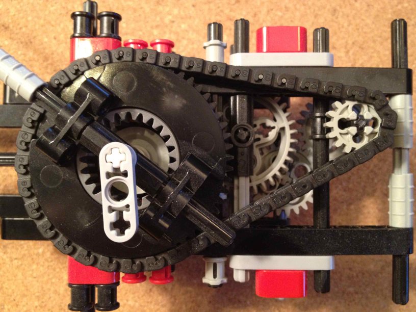
and viewed from the top they need to be like this:
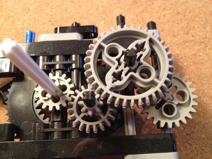
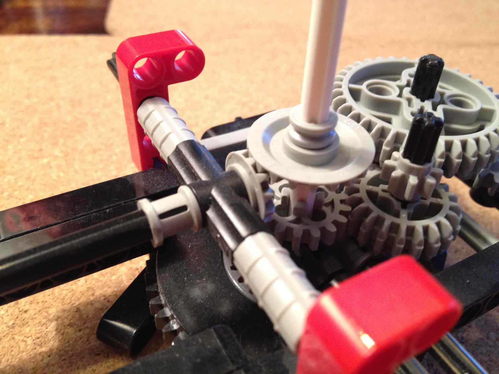
Here's another angle, which also shows the 20-tooth bevel gear that connects to the next part:
At this point you might want to turn the center axle (white in these photos) with your fingers, and adjust the alignments so that the gears meet each other properly and turn easily. You'll need to do that again a couple more times through the assembly process.
Next we add a horizontal axle that extends out the the end of the arm. This is used to make moons go around the planet (not shown here), and if you don't need moons around the planet it can be left out. Here are the parts:
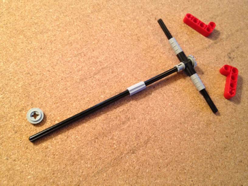
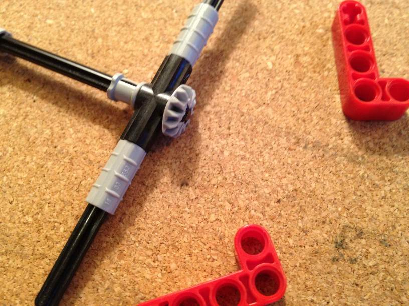
At the near end, there will be another bevel gear on the central axle that makes this horizontal axle turn:
A couple more views of what we have so far:
Now we need to add some more pieces to hold the top ends of the small axles for the gears, and a couple more gears:
This will be attached with these new pieces:
|


Here is a photo, before:

before
The new pieces in place, but not yet connected:

in position
... and now connected:

after
Once again, now you'll have to adjust things a bit so that all the gears turn smoothly.
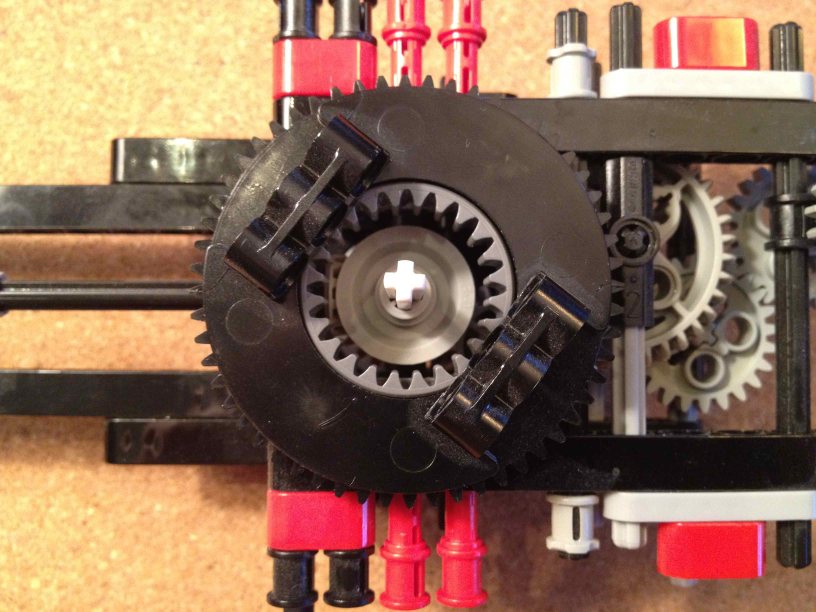
Now we're going to add the next turntable. It will be held in place with these red pins, and the last gear will make it turn with a chain:
Before:
Turntable in place:
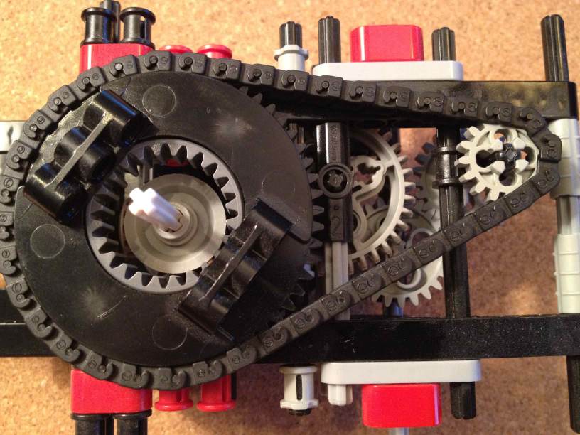
After adding chain:
Let's pretend this is the top layer, and the top planet doesn't have moons. Then all we need is something small that extends out like the hour hand on a clock. The black piece in the center allows the main axle to pass through and also keeps it steady.
After adding this bit:
Now is the time for final adjustments. The positions of the various gears can be adjusted so that almost no energy is lost to friction and vibration when it runs. Even though there is a 29-to-1 ratio between the big gear and the central axle, I can make the central axle run by turning the big gear! You can see this in my video showing this construction in action:
The center axle itself can have a "minute hand" to make its position obvious:
The finished module:

top view

side view

at an angle
Go back to main orrery page
Footnotes
1 : In a freak coincidence, I chose a bunch of gears to build this module without any regard for what the overall gear ratio would end up being. After I had the whole thing assembled, I did the math to work out what the ratio would be, and discovered I had created 29.53 purely by chance. It is mainly because of this coincidence that I have kept this module in case I ever decide to make a moon phase clock.
LEGO® creations index
The graph paper in my newer photos is ruled at a specing of 1 LSS, which is about 7.99 mm.
This site is not affiliated with the LEGO® group of companies.
LEGO®, Duplo®, QUATRO®, DACTA®, MINDSTORMS®, Constructopedia®, Robotics Invention System® and Lego Technic®, etc. are trademarks or registered trademarks of LEGO Group. LEGO Group does not sponsor, authorize or endorse this site.
All other trademarks, service marks, and copyrights are property of their respective owners.
If you want to visit the official LEGO® site, click here
Parts images are from LUGNET. On this page they explicitly give permission to link to the images:
Note: you may link (as in, Yes, it's OK) directly to these parts
images from an off-site web page.
This page was written in the "embarrassingly readable" markup language RHTF, and was last updated on 2013 Mar 11.
 s.27
s.27