Orrery Designs using LEGO® Elements
Since 2007 I have worked on Orrery designs using LEGO elements. This began when I looked at the NASA Kepler Mission website and found their educational material including a miniature tabletop "solar system" designed (in 2004) to demonstrate how the Kepler mission will work.
I liked their model so much I decided to work on a few improvements, then began developing my own completely new designs.
|
As this "page" has gotten rather long, I have broken up the material into a few pages, organized chronologically (oldest first).
Table of Contents
Constrained models (using parts from only two brand-new sets)
Model F: "Constrained" 5-Planet Design
G: Adding Moons and Refinements (Off-Road Truck rev. 2)
H: Finishing the Inner Planets (Off-Road Truck rev. 3)
More Fancy Ideas
The Hailfire Model: Extreme Co-planar Gears
Robust and Modular Designs
Stacked Turntables: Two-Module Prototype
Stacked Turntables: Four-Module Prototype
Appendices
Script for model D YouTube video
Script for Geartrain Module video
History: Previous Versions of the Orrery
20040915
My 2004 designs are descended from versions by Allan Ayres and Dave Koch. The first two were 2-planet and 3-planet designs by Ayres. I know little of the 2-planet version, but I suspect it was like its successor but without the middle planet.
Here is a picture of the 3-planet design; the building instructions for it are here: transitdemo.pdf.

A1. Ayres' 3-planet orrery
A large Technic turntable, whose base remains fixed, is made to turn through epicyclic gearing. 4 rotations of the inner shaft makes the turntable top rotate once. The 3rd planet is attached to the turntable, and the 1st planet to the central shaft. Another gear on the turntable makes the 2nd planet turn at a rate twice that of the 3rd.
The orbit period ratios can be measured easily just by turning the crank a few times. Here are the periods; I have also shown a "radius" computed by the formulas discussed here.
|
These orbital periods might seem a little artificial, but it does actually happen in real life — Jupiter's moons Io, Europa and Ganymede have exactly this ratio of periods, due to orbital resonance. You can approximate their orbits by setting up the model so that the 1st and 3rd planets are aligned and the 2nd is all the way around on the other side:
|

20050729
You may notice in the above 3-planet designs, there is a gear on the upper part of the differential housing that doesn't come into contact with any other gear. That gear provides an opportunity to add a fourth planet, and Dave Koch did exactly that. He took Ayres' 3-planet design and modified it to look roughly like this:
")
B1. My Rendering of the Ayres/Koch 4-Planet Orrery (without moon)
(Here, I have added half-stud adjustments to make the planet distances more closely conform with Kepler's 3rd law (discussed below).)
Then he added a moon:
")
Koch's version (with moon on 2nd planet)
|

These 4-planet designs incorporate two modifications over the 3-planet design:
- A new planet is added, carried by an arm with epicyclic gears that compute a weighted average of the rotations of its neighbors (details below). What were the 2nd and 3rd planets are now the 3rd and 4th, respectively.
- The differential housing is turned upside down, and gearing changed so that its rotation is slower (but still faster than that of the 4th planet).
The instructions to build this model are here: The Kepler Transit Demonstration
{Updated instructions for the Kepler project's 4-planet orrery are here: LEGOorrery2011.pdf -RPM 20121223}
Kepler's Third Law
To make the model more accurate, one should adjust the lengths of the arms so that the planets' distances are related to their orbital periods by the formula
(P/2π)2 = a3/(G(M+m))
where
P is the orbital period,
a is the semimajor axis of the orbit (the radius, for a circle)
G is the universal gravitational constant
M and m are the masses of the sun and planet
for our purposes we can simplify it to
a = K P2/3
where K is an arbitrary constant, which can be 1 if you express P and a as multiples of one planet's period and radius. So for example, knowing that Mars has an orbital period 1.88 times that of Earth, the formula tells us that its semimajor axis is 1.882/3 {~=} 1.523 times that of Earth.
All of the models above (A and my versions of B) are built with the proper distances to within ±2mm.
20071212
B's orbit periods are a bit more complex than A's. The turntable turns the same way as before, through epicyclic gearing. 12 turns of the crank make it go around once. This is one orbit of the 4th planet. 36 turns of the crank is the time it takes the 4th planet to orbit 3 times. In this period the 3rd planet orbits 4 times, the 2nd planet orbits 7 times, and the innermost planet orbits 12 times. I call this a syzygy cycle because if you start the orrery with all planets aligned, it takes this long for them all to become aligned again.
Here is a table showing the planet orbital rates and periods, and the radii used in Koch's model (K) and my two models (M1 and M2):
|
20071213
The number 7 in the above ratios might come as a bit of a surprise, if you consider that the gears (with 8, 16, 24 and 40 teeth) cannot by themselves produce any ratios involving the prime number 7.
The 7 (and other prime factors in the more complicated ratios below) comes from epicyclic gearing formulas that involve addition and subtraction, and division of ratios.
Consider first the drive of the 4th planet:

B2's Base.
This is a planetary gear mechanism (a type of epicyclic gearing). The base (black) is the annulus, and has 24 teeth. The planet-carrier (clear, and gray) carries the planet gear (blue) with it. The planet gear has 8 teeth. The sun gear (yellow) has 8 teeth. In this particular setup, the base is fixed, the sun is the input, and the planet-carrier is the output.
Let Rp be the rate of rotation of the planet-carrier, and Rs be the rate of rotation of the sun gear. Rb, the rate of rotation of the base, is fixed at zero.
It is easiest to compute the gear ratio from within the rotating reference frame of the planet. Relative to the planet, the base is rotating at -Rp and the sun is rotating at Rs - Rp. The base has 24 teeth, the sun has 8, and the planet acts as an idler gear. Because the base's gear is inside-out (teeth facing in) a direction reversal is added. The gear ratio is -1×24/8, or -3/1. Therefore, the motion of the planet-carrier and sun will fit the following formula:
Rs - Rp = -3 (-Rp)
and therefore (by algebra)
Rs = Rp + 3 Rp = 4 Rp
This shows that the 3rd planet in model A will revolve once for each 4 times the 1st planet revolves.
Notice that we get a ratio of 4, even though the gears we used (24 and 8) have a ratio of 3.
Now consider the transfer of motion to the 3rd planet:

B2 Transfer from 4th to 3rd
We will use R4 now to refer to the rotation rate of the 4th planet arm (Rp above), R1 instead of Rs, and R3 for the 3rd planet arm. Viewed from the rotating reference of the 4th planet's arm, this is an ordinary gear train. The sun gear (yellow) with 8 teeth drives a 24-tooth gear, which shares an axle with an 8-tooth gear (gray) which drives the output, a 24-tooth gear (dark gray). The input is R1-R4, the output is R3-R4, and the ratio is (-24/8)×(-24/8) = 9/1. Therefore:
R1-R4 = 9 (R3-R4)
we already know from above that R1 = 4 R4. So we have
3 R4 = 9 R3 - 9 R4
which gives
R3 = 4 R4 / 3
Still a fairly simple ratio, no strange prime numbers here. But let's see what happens when we go up to the 2nd planet:

B2's 2nd Planet Between 1st and 3rd
The 2nd planet's arm rotates at rate R2, and has gears mounted on it. The dark gray gear is turning at R3 — but from the 2nd planet's point of view, it rotates at R3-R2 (which is negative, hence backwards). The yellow gear rotates at R1, which is R1-R2 from the 2nd planet's point of view. An extra 16-tooth idler ensures that the gear train has only one direction reversal. The gear train will obey the equation
R1-R2 = (-40/24)×(16/16)×(R3-R2)
Which gear is the input? We already know that R1 and R3 are determined as just described. Therefore, they are both inputs, and R2, the 2nd planet's arm, is the output. The equation reduces as follows:
R1-R2 = -5 (R3-R2) / 3
4R4 - R2 = -5 (4R4/3 - R2) / 3
R2 - 4R4 = 20R4/9 - 15R2/9
24 R2 / 9 = 56 R4 / 9
R2 = 7 R4 / 3
There's that surprise prime number 7. Every time the 4th planet completes 3 orbits, the 2nd planet completes 7 orbits.
. . . Forward to page 2 . . . Last page (page 7)
LEGO® creations index
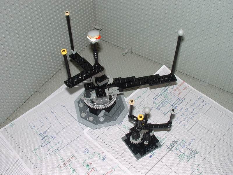
The graph paper in my newer photos is ruled at a specing of 1 LSS, which is about 7.99 mm.
This site is not affiliated with the LEGO® group of companies.
LEGO®, Duplo®, QUATRO®, DACTA®, MINDSTORMS®, Constructopedia®, Robotics Invention System® and Lego Technic®, etc. are trademarks or registered trademarks of LEGO Group. LEGO Group does not sponsor, authorize or endorse this site.
All other trademarks, service marks, and copyrights are property of their respective owners.
If you want to visit the official LEGO® site, click here
Parts images are from LUGNET. On this page they explicitly give permission to link to the images:
Note: you may link (as in, Yes, it's OK) directly to these parts
images from an off-site web page.
This page was written in the "embarrassingly readable" markup language RHTF, and some sections were last updated on 2015 Jan 11.
 s.27
s.27