All-LEGO® Stepper Motor
This is a simple subassembly I designed after being inspired by a discussion on LUGNETTM. This design is intended mainly to demonstrate the concept; if you were to use one as part of a complete project you would want to build a more compact version.
A "stepper motor" is a motor that can be made to move in precise steps. Usually they are used to control the position of something (like a turret, a camshaft, or an axis of a milling machine or plotter) where it is important to accurately and repeatedly achieve an exact position without using an input device to measure the position.
If you just want a good way to control motor speed (better than the 7 builtin "speeds" that are all about the same) check this page.
Most stepper motors are just simple modifications of 3-phase AC motors. They have 3 or 4 wires and require power in the form of three AC waveforms approximately 120o out of phase.
Making an ordinary motor (like the LEGO® motors) work like a stepper motor requires two things:
- A "centering" mechanism that pulls the motor into one or more positions in its rotation
- Software to drive the motor with "pulses" by turning it on for specific periods of time, to rotate from one "center" position to the next.
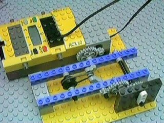
Here is a simple design that does this:

Overall view
The software (in NQC) that controls it is here.
The black square with the little white "clock hand" is there to show what position the device is in. Each time the motor moves one "step", the hand moves 1/9 of the way around its circle. That's 40 degrees per step, which is not very accurate for positioning a gun turret or a webcam — but if I wanted to use this for a real project I would add more gear reduction. That would give me greater resolution (more steps per revolution) and more torque.
The software allows the user to control the mechanism by sending commands 1, 2, and 3 from the remote control. Commands 1 and 2 move one step forward and back respectively, and command 3 moves 8 steps forward (leaving the "clock hand" in the same position that it would get to by sending command 2).
As written, the software sends pulses that are 0.09 seconds long. By trial and error I discovered that the pulse can be as short as 0.07 seconds and as long as 0.11 seconds and the stepper motor still works accurately. If there were more of a load on the motor, both values would be higher.
The continuous rotation task also sends 0.09-second pulses, and it waits 0.03 seconds between pulses. This produces accurate continuous motion at 8 steps per second. It could probably be a little faster (but not much). Of course, it can be slower — that's the point of stepper motors.
How it works
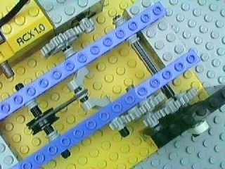
Here is a closeup of the mechanism:

Overhead view of the gearing
The motor (which is an old-style Technic motor) turns a camshaft via 1:3 gear reduction. The camshaft has an offset section that is 1 stud (8 millimeters) off center. A rubber band connects the offset section to a passive free rotating wheel. (This wheel must be able to turn freely because the rubber band turns a bit with each rotation of the camshaft.) As shown, the rubber band is under a very small amount of tension. If you are building this model you should make sure to use the same size rubber band — LEGO® makes several different sizes.
If the motor is run continuously (using the remote control's motor buttons or some other means) the rubber band provides resistance during half of the rotation and assistance during the other half. After the motor is stopped, the rubber band pulls the camshaft (either forwards or backwards, whichever is "easier") to the position shown here.
Therefore, you can make it "step" one revolution at a time by applying power for long enough to make it rotate more than 1/2 of a rotation but less than 1 1/2 rotations. This allows for a rather wide margin of error, which is important if the device is going to be moving a variable load (as would be the case, for example, if it were driving the vertical movement of a crane arm).
The camshaft drives a gear train which (in this example) produces 1:9 reduction. As I mentioned above, you would want to use more gear reduction in most applicaions because you want to control the rotation more accurately than 40 degrees per step.
If you build your own, you should do the same type of testing I did to determine the pulse length (this is the number used in the Sleep() command inbetween the Fwd() and Off() commands.) Start with a value like 10 and then increase or decrease the value in small steps. Once you know the highest and lowest working numbers, pick a number that is near the middle of the range. If you know your motor will have a greater load in actual use pick a slightly higher pulse length value. (However, the best approach for increased loads is to use more gear reduction.)
Modifications
If you want to build this design with the old motor like I did, you probably need to use exactly the same setup I did for the first three gears and the camshaft. I have tried different arrangements to get the motor more firmly secured to the rest of the construction, but almost everything I have tried adds enough friction that it doesn't work reliably. For example, attaching an axle extender to the motor and an axle that went through a hole in a beam was designed to help hold everything together, but it added just enough friction so that the motor couldn't always overcome the strength of the rubber band. I also tried putting extra 24-tooth gears between the motor's 8-tooth gear and the 24-tooth gear on the camshaft, but this also added too much friction.
My old Technic motor is very fast and very weak, and it seems to have a lot of internal friction during part of its rotation. It might be that you'll have better results with your motor, but if you have problems make sure to try the exact setup shown here before giving up completely.
The newer Technic motor moves slower and has more torque, and it shouldn't have this problem. However, you'll have to change the design. At a minimum, you'll need to eliminate the gear reduction between the motor and the camshaft. You might also have to make the rubber band stronger by using multiple rubber bands side by side.
If your software uses the Float() command instead of Off() to stop the motor, the motor's axle is able to "move free" when it stops rather than "putting on the brakes". This affects the pulse timings, and might also allow you to use a looser or weaker rubber band.
Initial Alignment and Recalibration
In some designs that use stepper motors, you need to have some kind of startup positioning or centering mechanism. This would be used once when the RCX starts up, because when you start up you don't know what position the stepper-controlled mechanism is in. You might also want to recalibrate at certain times. That's particularly important if there is a clutch in the geartrain to prevent the model from falling apart if something gets jammed.
Here are two simple types of recentering:
1. Clutch and Blocked Endpoints. You can use a clutch deliberately for recentering. This has the advantage that it doesn't use any kind of input and it also gives you the advantages of a fail-safe clutch design. To use a clutch for recentering, simply set up your model so there is something blocking some part of the full movement. Now you have a "blocked endpoint". When you start up, move in the appropriate direction for as many steps as it takes until you know for sure that you will have hit the blocked endpoint. Now you know where you are.
Note you need to use a real clutch (the white 24-tooth "gear" that comes with the motor set), not a rubber band linkage. Where to put the clutch in the geartrain is important — it has to be at a point in the geartrain where the clutch won't slip (not even a tiny bit) under normal use but it will slip when you hit the blocked endpoint(s) — and without having anything pull apart! Note that if the clutch experiences high acceleration (sudden starts or stops) it might slip a little bit. You'll probably want to try 2 or 3 different geartrain designs to find the best place for the clutch.
2. Shared Touch Sensor If you have an extra touch sensor, you can attach it to an input that is also used by some other sensor, and set it up so the touch sensor gets triggered when the stepped mechanism is in some specific little-used portion of its movement. If it's a rotating camera, for example, have the touch sensor trigger only when the camera is pointing backwards (or some other useless direction). That way, there's no problem sharing the touch sensor with another input because the touch sensor will not be touched during normal operation.
The graph paper in my newer photos is ruled at a specing of 1 LSS, which is about 7.99 mm.
This site is not affiliated with the LEGO® group of companies.
LEGO®, Duplo®, QUATRO®, DACTA®, MINDSTORMS®, Constructopedia®, Robotics Invention System® and Lego Technic®, etc. are trademarks or registered trademarks of LEGO Group. LEGO Group does not sponsor, authorize or endorse this site.
All other trademarks, service marks, and copyrights are property of their respective owners.
If you want to visit the official LEGO® site, click here
Parts images are from LUGNET. On this page they explicitly give permission to link to the images:
Note: you may link (as in, Yes, it's OK) directly to these parts
images from an off-site web page.
This page was written in the "embarrassingly readable" markup language RHTF, and was last updated on 2012 Dec 30.
 s.27
s.27