 |  |
|  | 
|
Screensavers by Robert Munafo
These are some live video effects created with Quartz Composer to demonstrate the use of the GLSL programming language to perform realtime calculation on live video images. Since that involves massive amounts of calculation, it's just the thing to keep me busy on an afternoon. GLSL and QC make it all really easy.
All of these screensavers are for the Mac, and take a live video input from a connected iSight camera or the built-in iSight camera in a portable Mac. They require Mac OS 10.6 or later to work as screen savers (put them in your Home/Library/Screen Savers directory). If you have the Developer Tools you can open the files in the Quartz Composer editor.
These have been tested with several different cameras in a variety of lighting environments, and handle very low and very high light conditions. Please let me know if you get a mis-exposed or otherwise boring image, a crash or some other issue.
Download links: GLSL-Mandelzoom Xmorphia PDE5 Video Life Video-Life (10.4 compatible) Acid Webcam My Evil Twin
(For each of these, right-click and choose "Download Linked File As..." or "Save Link As...". Put the QTZ file in your Home/Library/Screen Savers directory.)
Contents
GLSL-Mandelzoom
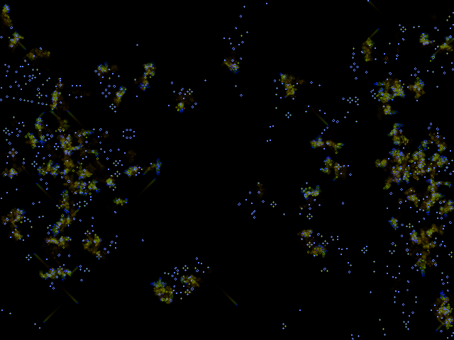
This is a Mandelbrot program using GLSL (OpenGL Shader Language) to do the calculations. It achieves over 11,500 iterations per second on a 1024x1024 image (about 109 GFLOPs) on the AMD Radeon HD 6750M in a 2011 model Macbook Pro.

GLSL Mandelzoom in Quartz Composer
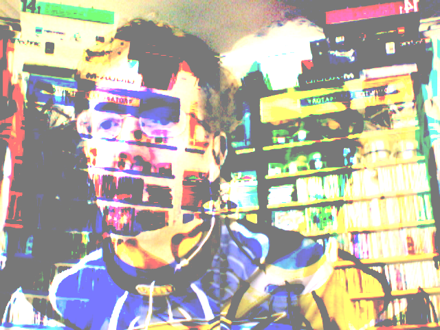
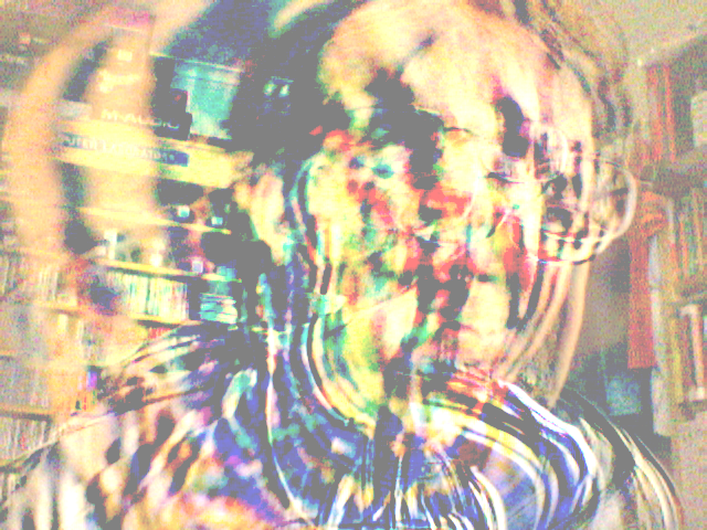
The user interface is through hand-waving to the webcam. The user holds his hands (or any bright object) in front of the screen, and the computer's built-in camera looks at hot regions (little squares in the bottom-left and bottom right of the thumbnail video images). The two squares make it zoom in or out. I compare the input pixels to the brightness, chroma and saturation of the back wall of the room. As you can see, wearing a dark blue shirt does not help (it is not "blue chroma-key").
The core iteration code is done with the following shader:
/* Mandelbrot iteration. The output needs to be fed back into the "image" input (via an accumulator); the second input "mod" holds per-pixel modifiers. image: r iteration count mods: r g g b current Zr b Cr a current Zi a Ci */ kernel vec4 iterate_C_Z(sampler image, float colorstyle, sampler mods) { vec2 c = samplerCoord(image); vec4 vars = sample(image, c); vec4 modv = sample(mods, c); float o_its = vars.r; float n_its = o_its; float zr = vars.b; float zi = vars.a; float cr = modv.b; float ci = modv.a; float bail=40.0; float absz2 = zr*zr+zi*zi; bool z_overflow = (absz2 > bail); // true if we will stop iterating this time vec2 z2, z3; z2 = vec2(zr*zr - zi*zi + cr, 2.0*zr*zi + ci); z3 = vec2(z2.x*z2.x - z2.y*z2.y + cr, 2.0*z2.x*z2.y + ci); absz2 = z3.x*z3.x+z3.y*z3.y; n_its = (absz2 < bail) ? n_its+2.0 : n_its; // . . . // Here there are 6 more copies of the above 3 lines // . . . z2 = vec2(zr*zr - zi*zi + cr, 2.0*zr*zi + ci); z3 = vec2(z2.x*z2.x - z2.y*z2.y + cr, 2.0*z2.x*z2.y + ci); absz2 = z3.x*z3.x+z3.y*z3.y; n_its = (absz2 < bail) ? n_its+2.0 : n_its; // send working variables back out, for us to use next time vec2 outz = vec2(z3.x, z3.y); // If we have overflowed, we return the original input values of Zr,Zi // in order to prevent iterating an overflowed value any higher vec4 rv = z_overflow ? vec4(n_its, 0.0, vars.b, vars.a) : vec4(n_its, 0.0, outz.x, outz.y); return rv; }
Other simpler kernels set up the grid with coordinate values, and convert the resulting iteration-counts into a nice color image. There is also a lot of code including a few shaders to implement computer-vision for the hand-waving interface.
I was planning to add more capability, in particular the ability to control pan and zoom by waving brightly-colored cards in various combinations, and removing the need for the hotspots to be in any particular part of the screen. I stopped working on it because I decided the Quartz Composer system was too limited for general-purpose computation, and accessing OpenGL directly through C was a better approach.
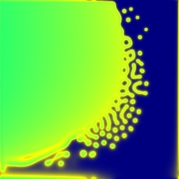
Xmorphia PDE5
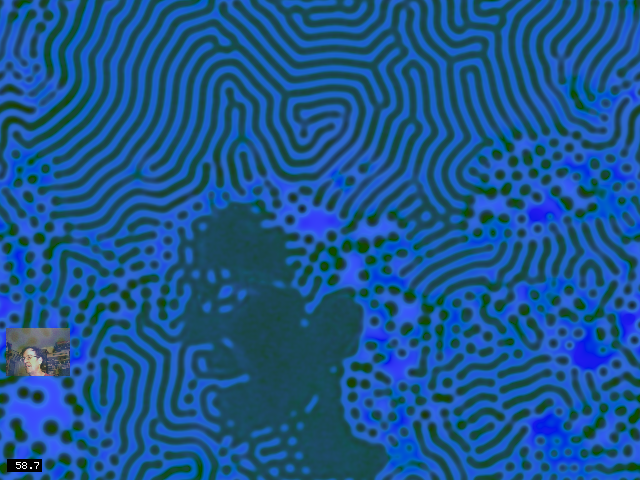
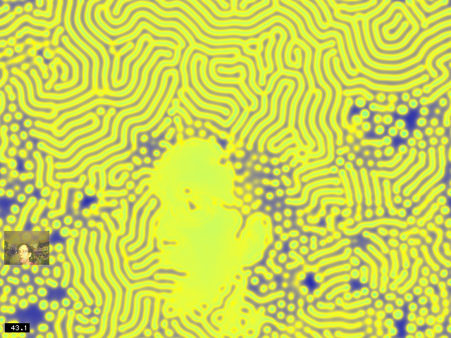
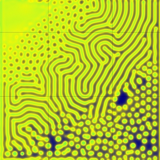
This is a screensaver implementation of the Xmorphia Gray-Scott reaction diffusion system, using the live video image to control the parameters k and F.

Xmorphia PDE5
 |  | 
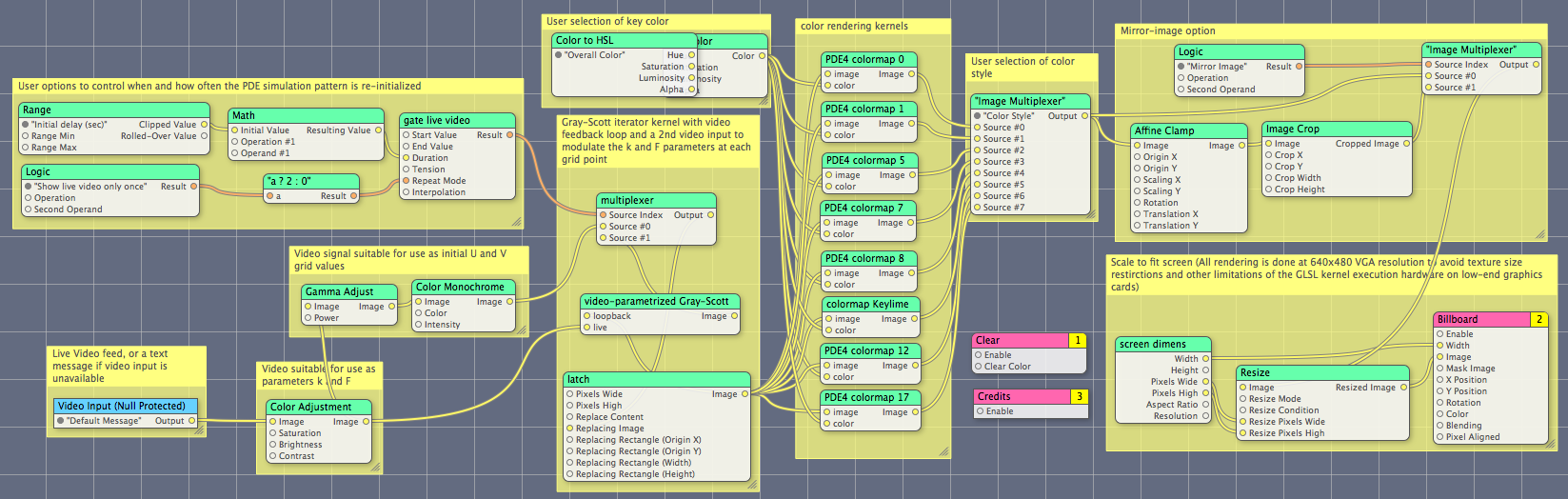
|
| 8 alternate color functions are available, and the key-color can be set separately. | ||
See my extensive Gray-Scott exhibit for background, many images and movies, and a lot more about the complex pattern-formation system used for this screensaver.
There are two GLSL shaders: one to create the color mapping from the problem variables u and v onto the blue and yellow colors you see, and the other (far more complex) to do the actual reaction-diffusion simulation. It is called a "PDE" simulator because the mathematics behind it is a pair of Partial differential equations.
The PDE shader takes two video inputs, one of which is itself (to keep track of the continually updating values of u and v throughout the grid); the other is the live video input, used to control the parameters k and F at each point in the image. This makes the video input subtly (or sometimes sharply) affect the behaviour of the patterns.
 |  | 
|
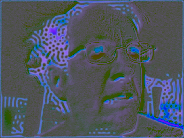
| Here it is set to color mode 3, which is the old PDE4 colormode 7 (left image). The color gamut of the input video image is mapped onto a section (right image) of the parameter space. All of the patterns seen in the center image can also be found in the right image (which is centered at parameter values k=0.055, F=0.025). | ||
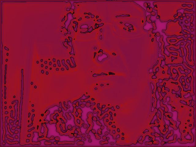
The initial values of U and V for the reaction-diffusion model come from a video image. They are created by converting the video image to grayscale, artificially enhancing its contrast, and mapping brightness values in the range (0.0, ..., 1.0) onto a range of U and V values that occur frequently in actual patterns.
/* Convert an RGB signal (with components that range from 0 to 1) into a range of u/v tuples suitable as an initial Gray-Scott pattern in the region around k=0.058, F ranging from 0.02 to 0.04. input: r \ output: r u g |video g v b / image b 0 (unused) a a 1 (presently unused) */ kernel vec4 gray_scott_initial_UV(sampler live) { vec2 c = samplerCoord(live); vec3 live_video = sample(live, c); /* This is the luma (Y) component of a RGB to YUV transform */ vec3 rgb_luminance = vec3(0.30, 0.59, 0.11); float val = dot(rgb_luminance, live_video); /* artificial contrast enhancement to produce a useful image even when the image is fairly dark */ val = mod(7.0 * val, 1.0); /* Map the values (0.0 .. 1.0) in a parametrized way onto (u,v) tuples from [(0.3, 0.3) .. (1.0, 0.0)] */ float u = 0.3 + 0.7 * val; float v = 0.3 * (1.0 - val); vec4 retval = vec4(u, v, 0.0, 1.0); return(retval); }
The result of that kernel is a contrast-enhanced image:

Input pattern
A pattern like this is presented to the following kernel's "live" input, with its own output as the "loopback" input:
/* Gray-Scott reaction diffusion system. See mrob.com/sci One should feed the output of this kernel back into the "loopback" input, and attach an iSight or other video input to the "live" input. loopback r U I/O live r F I g V I/O g k I b Du O b - - a - - a - - */ kernel vec4 gray_scott(sampler loopback, sampler live) { vec2 c = samplerCoord(loopback); vec2 sz = samplerSize(loopback); vec2 cup = vec2( c.x, (c.y+1.0 > sz.y) ? c.y+1.0-sz.y : c.y+1.0); vec2 cdn = vec2( c.x, (c.y<1.0) ? c.y+sz.y-1.0 : c.y-1.0); vec2 crt = vec2((c.x+1.0 > sz.x) ? c.x+1.0-sz.x : c.x+1.0, c.y); vec2 clt = vec2((c.x<1.0) ? c.x+sz.x-1.0 : c.x-1.0, c.y); // "Pearson" model from PDE4 float dt = 1.0; float dxy = 2.5 / 256.0; float Du = 2.0e-5; float Dv = 1.0e-5; // U and V are kept in the first two components (r/g or x/y) of the pixel vec2 uv = sample(loopback, c); vec3 live_video = sample(live, c); float u = uv.x; float v = uv.y; float F = live_video.r; float k = live_video.g; vec2 del = sample(loopback, cup) + sample(loopback, cdn) + sample(loopback, crt) + sample(loopback, clt) - (4.0 * uv); del = del / (dxy * dxy); float du = dt * ((Du * del.x) - (u * v * v) + F*(1.0-u)); // u1 is the delta, and output.x will be uv.x + u1 float u2 = u + du; u2 = clamp(u2, 0.0, 1.0); float v2 = v + dt * ((Dv * del.y) + (u * v * v) - (F+k)*v); v2 = clamp(v2, 0.0, 1.0); // output.y will be v1 vec4 retval = vec4(u2, v2, du, 1.0); return(retval); }
There are eight (8) more shaders for color-mapping. Each implements a function that converts from raw u and v values used for the simulation to red/green/blue values needed for display, and all of them obey the "Overall Color" parameter that gives the user additional aesthetic control. I will show two representative examples.
This is the shader for the colormap that is used in the sample screen images shown on this webpage. (In the screensaver options, this is color style 3):
/* PDE4 colormap 7 */ kernel vec4 PDE4_colormap_7(sampler image, __color color) { vec2 c = samplerCoord(image); vec4 i1 = sample(image, c); float t2 = i1.r; float t3 = i1.g; t2 = 1.0 - t2; float t4 = 1.0 - t3 - 0.5*t2; t4 = (t4 < 0.0) ? 0.0 : t4; vec4 vc = (t4 > t2) ? vec4(1.0 - t4 + t2, 1.0 - t4 + t2, 0.5*(t4-t2), 1.0) : vec4(1.0 - t2 + t4, 1.0, 0.5 * (t2 - t4), 1.0); // Finally multiply by the user's chosen colour and ensure alpha is 1.0 vc = vc * color; vec4 o1 = vec4(vc.r, vc.g, vc.b, 1.0); return o1; }
And here is the shader for the colormap used in my main Xmorphia exhibit, which includes its own HSV to RGB conversion function. (In the screensaver options, this is color style 7):
/* PDE4 colormap 17 */ vec4 go_hsv2rgba(float h, float s, float v, float a) { float i = floor(h); int ii = int(i); float f = h - i; float p = v * (1.0 - s); float q = v * (1.0 - s * f); float t = v * (1.0 - s * (1.0 - f)); vec4 rgba = (s <= 0.0) ? vec4(v, v, v, a) : ((ii == 0) ? vec4(v, t, p, a) : ((ii == 1) ? vec4(q, v, p, a) : ((ii == 2) ? vec4(p, v, t, a) : ((ii == 3) ? vec4(p, q, v, a) : ((ii == 4) ? vec4(t, p, v, a) : vec4(v, p, q, a) ))))); return rgba; } kernel vec4 PDE4_colormap_17(sampler image, __color color) { vec2 c = samplerCoord(image); vec4 i1 = sample(image, c); float t2 = i1.r; float diff = i1.b * 75.0 + 0.5; diff = (diff > 1.0) ? 1.0 : ((diff < 0.0) ? 0.0 : diff); float t1 = 0.25 + diff * 0.6; float t4 = 1.0 - t2; t4 = t4 + 1.98; t4 = t4 - floor(t4); vec4 vc = go_hsv2rgba(6.0 * t4, t1, 0.25 + 0.5*t2, 1.0) * color; vec4 o1 = vec4(vc.r, vc.g, vc.b, 1.0); return o1; }
Download: Xmorphia PDE5 (right-click and "Download Linked File As..." or "Save Link As...")
Video Life (created with the help of Michael Ash2)
")
Video Life (capturing)
 have become a Life pattern")
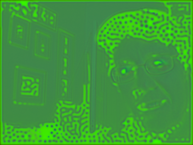
Edges (mouth, eyes, etc.) have become a Life pattern
Video Life takes a picture with the iSight camera every 20 seconds, then spends approximately 18 seconds animating the resulting image using Conway's Game of Life.
The shader code was written by Michael Ash:
kernel vec4 conway_life(sampler image) { vec2 c = samplerCoord(image); vec2 cup = c + vec2(0.0, 1.0); vec2 cdn = c + vec2(0.0, -1.0); vec2 crt = c + vec2(1.0, 0.0); vec2 clt = c + vec2(-1.0, 0.0); vec2 cur = c + vec2(1.0, 1.0); vec2 cdr = c + vec2(1.0, -1.0); vec2 cul = c + vec2(-1.0, 1.0); vec2 cdl = c + vec2(-1.0, -1.0); float accum = 0; accum += step(0.5, sample(image, cup).b); accum += step(0.5, sample(image, cdn).b); accum += step(0.5, sample(image, crt).b); accum += step(0.5, sample(image, clt).b); accum += step(0.5, sample(image, cur).b); accum += step(0.5, sample(image, cdr).b); accum += step(0.5, sample(image, cul).b); accum += step(0.5, sample(image, cdl).b); vec4 retval = sample(image, c); float center = step(0.5, retval.b); float thresholdLow = (center > 0.5 ? 2.0 : 3.0); float thresholdHigh = 3.0; float alive = (accum <= thresholdHigh ? (accum >= thresholdLow ? 1.00 : 0.0) : 0.0); retval = vec4(alive); retval.a = 1.0; return retval; }
I then modified it somewhat to create the following display with faint, fading trails where the cells are active, and solid color where any cells have stopped changing:
Video Life with trails
The shader code for this modified version is:
/* Conway's Game of Life on an input image. Ordinarily one would feed the output of this kernel back into itself (via an accumulator) */ kernel vec4 conway_life(sampler image, float do_trails) { vec2 c = samplerCoord(image); vec2 cup = c + vec2( 0, 1); vec2 cdn = c + vec2( 0, -1); vec2 crt = c + vec2( 1, 0); vec2 clt = c + vec2(-1, 0); vec2 cur = c + vec2( 1, 1); vec2 cdr = c + vec2( 1, -1); vec2 cul = c + vec2(-1, 1); vec2 cdl = c + vec2(-1, -1); // The threshold varies from top to bottom of image: this allows us to // get something interesting regardless of the exposure adjustment of // the camera float thr = c.y / samplerSize(image).y; float accum = 0; accum += step(thr, sample(image, cup).b); accum += step(thr, sample(image, cdn).b); accum += step(thr, sample(image, crt).b); accum += step(thr, sample(image, clt).b); accum += step(thr, sample(image, cur).b); accum += step(thr, sample(image, cdr).b); accum += step(thr, sample(image, cul).b); accum += step(thr, sample(image, cdl).b); vec4 prevcell = sample(image,c); float center = step(thr, prevcell.b); float thresholdLow = 3.0 - center; float thresholdHigh = 3.0; float alive = (accum <= thresholdHigh ? (accum >= thresholdLow ? 1.00 : 0.0) : 0.0); vec4 retval = vec4(0.95 * prevcell.r + 0.1 * prevcell.g, 0.95 * prevcell.g + 0.1 * prevcell.a, alive, 0.95 * prevcell.a + 0.1 * prevcell.b); vec4 ret_simple = vec4(alive, alive, alive, 1.0); return ((do_trails > 0.5) ? retval : ret_simple); }
The modified shader sets a threshold that varies with the row address (y coordinate) which makes it less sensitive to the exposure/brihtness of the camera image (this is a problem with the original version). The fade effect also required adding a Clear patch behind the main Billboard because I use the alpha channel to carry information. I also had to increase the bit depth of the Accumulator patch from 8 to 16.
Finally, I added options to turn the trails off, set the overall color, and alter the length of time between live video snapshots.
Download: Video Life (plain) Video Life (with trails option) (right-click and "Download Linked File As..." or "Save Link As...")
Acid Webcam
Acid Webcam
This one demonstrates the use of a feedback loop to make an image that depends both on the live video input and on its own previous contents. Here is the essential texture shader code (kernel):
/* Feed the output of this kernel back into its "loopback" input, and feed an iSight input into the "live" input. */ kernel vec4 acid_video(sampler loopback, sampler live, __color color) { vec2 xy = samplerCoord(live); vec4 prev = sample(loopback, xy); vec4 now = sample(live, xy); vec4 next; next = now - (0.99 * prev); return next; }
Download Acid Webcam (right-click and "Download Linked File As..." or "Save Link As...")
My Evil Twin
My Evil Twin
This is similar to Acid Webcam, and really only demonstrates one additional thing, which is flipping the horizontal sampling coordinate to create a mirror image. If your iSight is located right above your display (as on a iMac or MacBook) it is set up to appear that you are looking in a mirror and your "evil twin" is flipped the other way. (Notice that I need to use flipped coordinates for both inputs — you might wish to speculate as to why).
Although it may appear at first glance that this is just a positive image on the left and a negative on the right, the image actually has both positive and negative everywhere. For example, you can see all four shoulders, and both heads are transparent.
Here is the shader:
/* Feed the output of this kernel back into its "loopback" input, and feed an iSight input into the "live" input. */ kernel vec4 acid_video(sampler loopback, sampler live, __color color) { vec2 xy = samplerCoord(live); vec2 nxy = vec2(640.0-xy.x, xy.y); vec4 prev = sample(loopback, nxy); vec4 now = sample(live, nxy); vec4 next; next = now - (0.9 * prev); return next; }
Download My Evil Twin (right-click and "Download Linked File As..." or "Save Link As...")
Footnotes
1 : There is also a Quartz Composer in the MacOS 10.4 developer tools. The download links above are files that do not open in the 10.4 version of Quartz Composer.
However, here is a 10.4 compatible version of Video-Life (right-click and "Download Linked File As..." or "Save Link As..."). You cannot use it as a screen saver, but you can at least open it in the editor and watch it in the viewer window. Just for fun, the credits zoom away from the camera instead of fading out.
2 : Thanks to Michael Ash, who showed me a Quartz Composer module he had created that simulates Conway's Game of Life. I turned it into a screensaver and added the use of live video, color, "trails" and the caption text. Then I created the other screensavers you see here.
(Answers are "hidden" below)
Answers
Why do you need to flip the coordinates on both video inputs in My Evil Twin?
Because the output is fed back into the input.
The x coordinate of the "live" input is flipped because we want the "non-evil twin" (the positive video image) to be like looking in a mirror (if you have used Photo Booth program you may have noticed this).
The "loopback" input comes from our own output, which contains a mirror-image of the positive "non-evil twin" image. But we want the Evil Twin to be flipped the other way, thus it has to be a non-mirror image. So, when sampling the loopback texture we need to use the same flipped x coordinate as was used to sample the live texture.
This page was written in the "embarrassingly readable" markup language RHTF, and was last updated on 2018 Feb 04.
 s.27
s.27