Building Instructions for RILYBOT 2
Look here for a general description of this robot and pictures of the fully-assembled model.
Special parts used for this model:
- Three motors, new Technic style (the old motors won't work because there is no gear reduction)
- Some Throwbot leg and ankle joints. They are used to attach the RCX to the bottom of the frame; if you don't have any you can just tie it in place with string (unless you're a purist!)
- Eight #16 beams. The yellow beams I used here come from the 8250 Search Sub kit.
Let's get started!
Start with the tire that is 30 mm in diameter and 10 mm wide. Put it on the standard "small" hub:
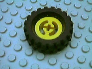
The wheel used for RILYBOT 2
Put the wheel on a #8 axle. Orient it so the wider part of the tire sticks "out" as shown. Use two half bushings on this side, and a normal bushing on the other:
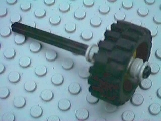
Wheel and tire with #8 axle and bushings
You will need to build two of these braces. Each one uses a 3x7 angle beam, two black friction connector pegs, a #3 axle, a #1 connetor brick and two half-bushings:
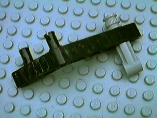
An angle-beam brace
Add the first angle-beam brace and two half-bushings to hold it in place. (A normal bushing isn't nearly as strong as two half-bushings and might not be enough to keep the wheel from slipping):
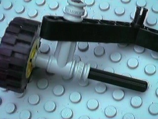
After adding first angle beam brace and two half-bushings
Add a #10 axle with an axle extender:
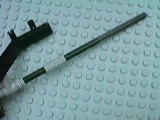
The axle extended
Then slide the second angle-beam brace onto the axle:
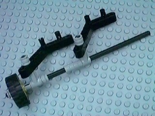
After sliding the second angle-beam into place
Now attach a #16 beam to the two angle beams. Put a #3 friction connector through the last hole on the other end of the beam so it sticks out on both sides:
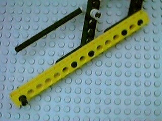
The #16 beam connected to the wheel/axle assembly
Now get a second #16 beam, and attach two black friction connectors and two catch cross pieces with a #3 axle to make this:
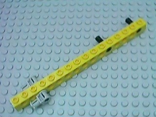
The second #16 beam
Now connect the two beams. They should go side-by-side, and "overlap" by 4 studs:
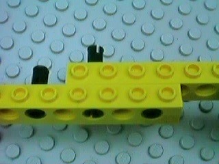
After attaching the second beam to the first
Then add two 2x4 Technic plates (or normal plates), one on top and one on the bottom:
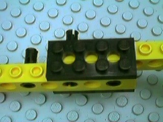
With two 2x4 Technic plates in place
The whole assembly, so far, will look like this:
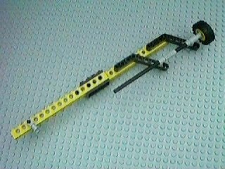
Full view of leg after connecting the two beams
Now it's time to build the motor assembly. There are four pieces.
The first piece is the motor itself. Attach a 9V connecting cable as shown (you want to use the ones that are about 20 cm long). Also attach an axle extender to the motor's axle.
The second piece is made from a 2x4 Technic plate, a #3 cross axle with stud (the dark gray one) and two 1x2 plates.
The third piece is a #2 beam with one 1x2 plate on top and a black friction connector peg.
The fourth piece is a #2 beam with two 1x2 plates on top and a black friction connector peg.
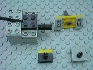
The four pieces of the motor assembly
Complete the motor assembly by attaching the four pieces so the result looks like this picture. Notice that both friction connectors have to point "out", and the one with two 1x2 plates goes on the "right":
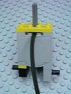
Completed motor assembly viewed from the "back"
Attach the motor assembly to the axle. From the side it should look like this:
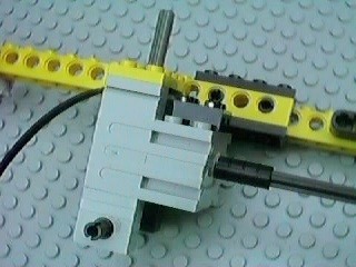
Motor assembly attached to axle.
Now attach the motor to the long beam. If it's lined up right it will end up looking like this from the "top":
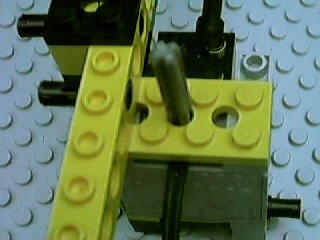
Motor assembly attached to leg
Next, add a #12 beam, which will become a cross-brace that holds the legs to each other:
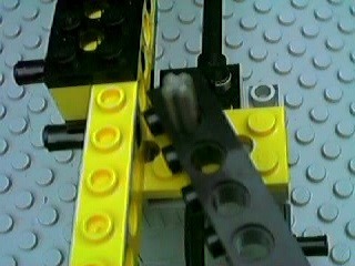
#12 cross-brace beam in place
Then add a 2x4 Technic plate:
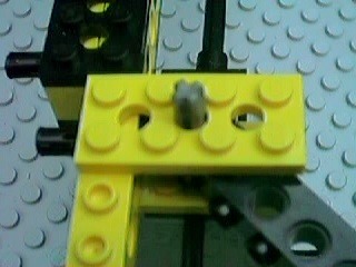
With 2x4 plate
Then add a half bushing, a #2 beam and a black friction connector peg:
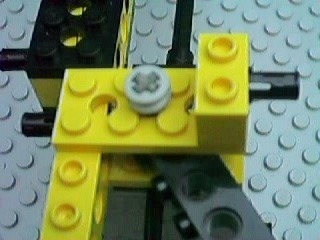
With half bushing, #2 beam and friction peg in place
Now it's time to brace the motor and attached bricks. For this you need a #8 beam and a #10 beam:
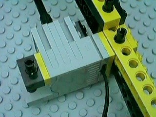
One side of the motor assembly. A #8 beam will go here.
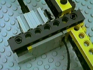
#8 beam brace in place
Now brace the other side of the motor assembly in the same way, but using a #10 beam:
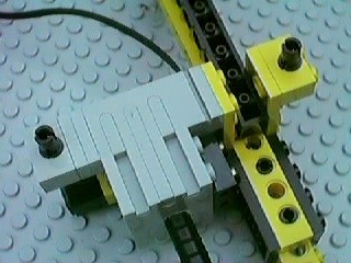
The other side of the motor assembly. A #10 beam will go here.
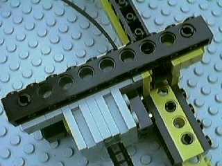
#10 beam brace in place
Congratulations! You've finished one third of the robot. Now you just have to do the same thing two more times.
When you're done, you should have three identical motorized legs that each look like this:
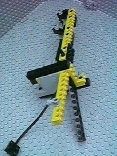
One complete motorized leg assembly
Now it's time to assemble the three legs into a robot. The end of the leg with the wheel is the bottom, and the other end is the top. Look at this picture carefully. The three legs need to be aligned just as shown in the picture. If they're aligned properly, each leg can be attached to the other two by adding two #3 cross axles as shown in the following pictures (you'll use six #3 cross axles and six bushings).
The two #3 cross axles that you need to add are highlighted in red:
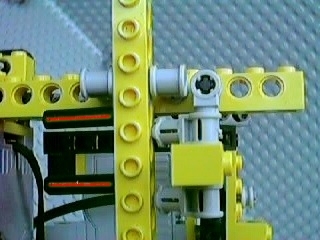
The tops of the legs (almost) aligned, and two #3 cross axles being inserted from the left into the vertical yellow beam
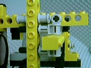
After fully inserting the two #3 cross axles
When you're doing this, you don't have to try to hold all three legs in place at once. Just connect the first two, then add the third leg, then add the final pair of #3 cross axles.
Then you add a full bushing to each cross axle to hold it in place:
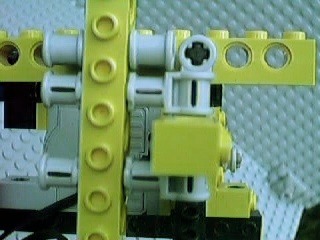
The 3-way joint connection, fully assembled
Now connect the cross-braces. Each leg should have one remaining unused black friction connector. This connector goes in the last hole of the cross-brace:
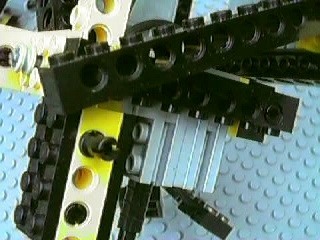
Before
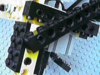
After (do this 3 times)
Now you want to build the suspension arms for the RCX. You need to make four arms. Each arm uses one Throwbot "leg" piece (the piece with a ball joint on each end) and two Throwbot "ankle" pieces (the black pieces in the picture connected to the balls). You also need a #3 or #4 cross axle and bushings or half-bushings to connect the top to the leg, and a gray axle-connector peg for the bottom end. Build each arm as shown in the picture:
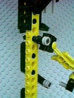
One suspension arm connected to a leg
All four arms have to attach to a leg in the manner shown. Since there are only three legs, two of the suspension arms share a leg. This is done by using a #4 cross axle so you can attach both suspension arms to either side of the leg. The leg with two suspension arms will become the "front" of the robot as shown in most of my pictures on the RILYBOT 2 page.
Take two more #16 beams, and add two dark gray 3/4 connecor pegs to each of them, to make two of these (count the holes to position the connector pegs properly):
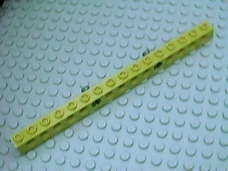
Bracket beam for the RCX (2x)
The end that will go towards the "front" is the end in the lower-left corner. This end has five empty holes before the first 3/4 connector peg; the other end has only four.
Connect the beams to the ends of the suspension arms. The beams should be parallel, and horizontal when the robot's three wheels are on the ground. They should also be running "front-to-back", and the spacing between them should be about right for an RCX. The 3/4 connector pegs should point "in". To get the beams to line up right you might have to change the suspension arms a bit — each suspension arm ends up being a little different. The ball-and-socket joints give you most of the flexibility you need to make it work.
Feed the three motor connectors through the space between the three motors, so they can be connected to the RCX which will be between the two long beams. For convenience you might want to attach a 2x6 plate to the three motor connectors. This makes it easier to remove the RCX from the robot if you are going to be using the RCX in other projects:
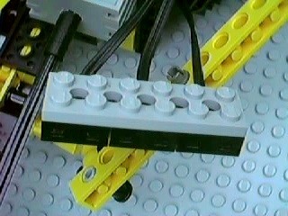
Holding the three motor cable connectors together
Finally, connect the RCX in between the two beams and attach the three motor connectors to the RCX.
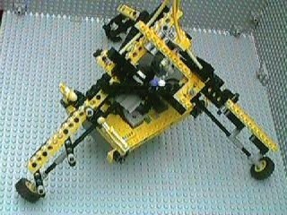
Completed model (with minifig and antenna decoration)
Two pictures of the minifig and antenna decorations are at the bottom of this page.
This robot does not (currently) use any sensors. Its RCX program is designed to move in response to commands from the RCX infrared remote control.
Return to: RILYBOT 2 page
The graph paper in my newer photos is ruled at a specing of 1 LSS, which is about 7.99 mm.
This site is not affiliated with the LEGO® group of companies.
LEGO®, Duplo®, QUATRO®, DACTA®, MINDSTORMS®, Constructopedia®, Robotics Invention System® and Lego Technic®, etc. are trademarks or registered trademarks of LEGO Group. LEGO Group does not sponsor, authorize or endorse this site.
All other trademarks, service marks, and copyrights are property of their respective owners.
If you want to visit the official LEGO® site, click here
Parts images are from LUGNET. On this page they explicitly give permission to link to the images:
Note: you may link (as in, Yes, it's OK) directly to these parts
images from an off-site web page.
This page was written in the "embarrassingly readable" markup language RHTF, and was last updated on 2012 Dec 30.
 s.27
s.27